
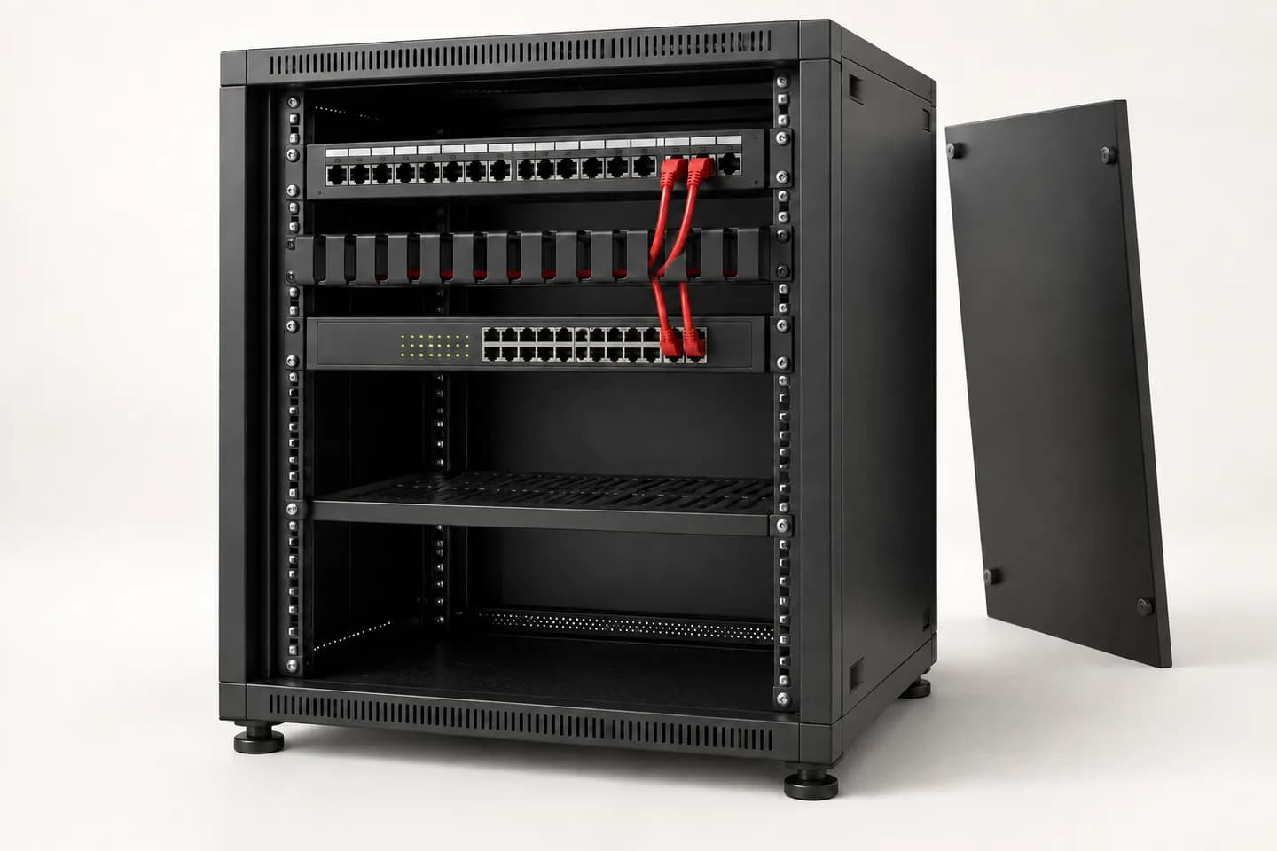
Prepare my site brief: worksheet and printable PDF
01
Start with the actual route, not the cable reel.
For every link, name the origin, destination and intended service. Survey possible routes, penetrations, access and retained sections. Distinguish a plan distance from a measured cable route: installation allowances and routing constraints should be explained, not hidden in a total quantity.
Describe the route environment: indoor, outdoor, moisture, condensation or sunlight. A conduit or shelter does not automatically make indoor cable suitable outdoors. Confirm the reference for actual conditions and applicable building requirements.
02
A complete link, from port to endpoint.
Define the tested scope: installed link or channel including patch leads. The report must identify what was measured; a test does not cover components added afterwards.
01 · Active equipment
The switch’s copper or optical port and exact interface. A module cage alone does not establish supported link types.
02 · Patching
An identified patch lead to the panel or fibre enclosure. The panel organises terminations; it does not replace the switch handling communication.
03 · Installed link
Cable and terminations labelled at both ends. Document joints and intermediate components instead of omitting them from the final plan.
04 · Destination and device
Remote outlet or termination, final patch lead and endpoint. Record destination power needs and connector clearance.
05 · Labelling and acceptance
Associate each identifier with the plan, port and test report. Deliver results, outstanding issues and corrections, not just a tidy-rack photo.
03
Compare complete paths, not isolated connectors.
Scroll the table horizontally to compare all three columns.
| Topic | Selection question | Required check |
|---|---|---|
| Copper or fibre | Which service, route and endpoint interfaces? | Validate the medium and complete-link limits for the references and project. |
| Optical modules | Which device, fibre type and terminations exist? | Confirm module/host support, rate, documented reach, connectors and both ends’ match; form factor alone is insufficient. |
| Shielding | Which interference constraints and connection system are planned? | Assess cable, connectors and installation together. Have earthing provisions validated by a qualified professional. |
| Rack and access | What height, depth, load and access are actually required? | Check mounting, usable depth and cable clearance with doors closed. Include equipment ventilation and maintenance needs. |
| Reuse | Are labels, references and test results available? | Separate verified items from those needing checks. A link working today does not establish every future use. |
04
Example: trace office B07 without guesswork.
ILLUSTRATIVE EXAMPLE
Fictional single link between rack B1 and office B07. Labels illustrate documentation, not a mandated convention or certified performance.
Assign a stable identity
The brief maps B1-PP1-07 to panel PP1 port 07 and outlet B07-A. The plan ties both ends together. The switch port is recorded separately because patching can change without changing the installed cable.
Define the agreed test
The report records the identifier, measured scope, method, result and date. A continuity check does not become bandwidth certification. An untested link remains explicitly unverified at handover.
Update after a change
If the workstation moves to another port, update the patching table and relevant network permissions. Retain the intervention record and associated report. The next technician should trace the path without disconnecting devices to guess.
Labelling does not establish electrical or optical quality. Measurement methods and criteria must match the medium and agreed outcome.
05
Six questions before the bill of materials.
Which origins and destinations?
List outlets, racks, buildings and services with planned additions. Separate retained items, items needing checks and new links.
Which routes and environments?
Plans, surveyed lengths, penetrations, access, moisture and building constraints. Have the project owner identify applicable requirements.
Which exact interfaces?
References for switches, modules, panels, outlets and patch leads. Specify included and missing parts instead of buying a similar-looking connector.
What complete space requirement?
Rack layout including devices, supports, power, cabling and reserves. Also check delivery-door clearance, opening and maintenance access.
Which tests and deliverables?
Scope, method, criteria, labels and report format. Request a final dossier matching what is actually installed.
What installation schedule?
Occupied areas, authorised outages, dependencies and contacts. Separate supply, installation, testing and handover so every responsibility is visible in the offer.
06
Documented infrastructure, without compliance shortcuts.
A cable-category name, common connector or rack photograph does not validate the whole installation. Characteristics must come from selected references; installation rules and tests must be defined for the site. Inovexia receives equipment and document enquiries. Work, checks and attestations must be explicitly assigned to competent parties.
07
Purchasing mistakes to avoid.
Does fibre also carry PoE?
The optical link does not supply electrical PoE power. Specify how the remote equipment is powered; any converter and its own power supply belong in the diagram and quotation.
Are modules fitting the same port interchangeable?
Not necessarily. Check host support, optical characteristics, fibre and the opposite end. Keep confirmations for exact references rather than extrapolating to a whole range.
Does a patch panel add active network ports?
No. It organises passive links. Simultaneous use of connected outlets requires active ports and matching patch leads; document their assignments separately.
Is available height enough to select a rack?
No. Check usable depth, mounting, load, cables, ventilation and maintenance access. A short-height device may still lack space behind its connectors.
Can cabling without an old report be retained?
Its condition remains to be established. Identify links and agree checks for intended uses. Quote checks and potential replacements separately; do not declare unexamined items compliant.
Technical sources
External reading references. These documents explain principles; they do not certify catalogue products or their combination.
- Indoor vs. Outdoor Cables — Which Should You Choose?Belden · Sources consulted on
- Shielded and Unshielded Category Cable for AVBelden · Sources consulted on
- Demystifying Fiber Test Methods — Back to BasicsFluke Networks · Sources consulted on
- Maximum equipment and cable mounting depth for NetShelter WXSchneider Electric · Sources consulted on